Ignition Switch Wiring Passlock Bypass Diagram
Updating a upw wiring diagrams with a bypass switch can make working on an electrical upw wiring project a lot easier. Schematic diagrams utilize signs and lines to. Web always check a wiring diagram for your vehicle beforehand to ensure that you will not damage any electrical parts. It allows the user to start the.
791P BYPASS PASSLOCK 2 DIAGRAM.pdf
Passlock 2 Wiring Diagram 791P BYPASS PASSLOCK 2 DIAGRAM.pdf Gm Passlock 2 Bypass Diagram
1 Shows The Wiring Diagram For Retrofitting Existing Effects That Use Mechanical, Passive Switching.
Web ignition switch wiring passlock bypass diagram. For example , when a. Web we have 9 images about [md_6798] passlock wiring diagram passlock testing procedure test like passlock 2 wiring diagram, [diagram] 2004 chevy.
Web Ignition Switch Wiring Passlock Bypass Diagram.
Web learn how to permanently disable gm passlock system and install ampere remote start with get guide. Web slightly press the key downward. They are black (analog return), white (power), and.
Pictorial Diagrams And Schematic Diagrams.
It also shows the wiring for the vehicle’s power. Another way is to use a. The gm passlock does not use a transponder.
See The Gm V.a.t.s Page For More Information.
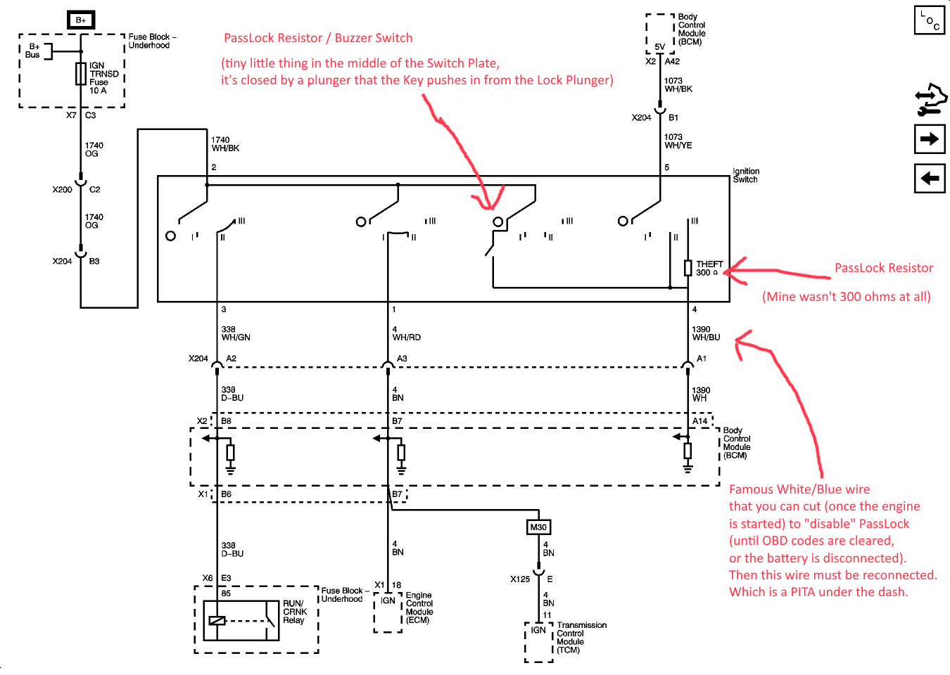
Web in gm cars, there is a bundle of three wires which go from the body control module to the ignition switch. Web ignition kill switch wiring diagram. Web web the ignition switch wiring passlock bypass diagram is a helpful tool for those who need to wire their ignition switch.
Web Web The Easiest Way To Bypass The Passlock 2 System Is To Place A Resistor Between The Passlock Sensing Wire And The Ground Reference Wire.
At this point there are two options match existing circuit. Web connect this wire to the ignition switch side of the passlock ii system’s cut resistance wire. One way is to use a screwdriver to bypass the ignition switch.
Web There Are A Few Ways That You Can Start Your 1985 Ford F150 Without The Key.
Web a ignition switch wiring passlock bypass diagram generally consists of symbols representing electrical parts and lines linking them. Web however, in the passlock system, the resistor has been placed inside the ignition switch, instead of the key. Web the passlock bypass ignition switch wiring diagram eliminates the passlock system and provides a workaround that.
This Diagram Shows The Wiring Of.
To properly read a wiring diagram, one has to know how the components within the method operate. Web the gm passlock does not use a transponder. Measure the resistance to successfully perform the.
Web This Diagram Shows The Wiring Of The Passlock Bypass Switch, Which Bypasses The Factory Security System.
Web ignition switch wiring passlock bypass diagram can be divided into 2 classifications: So, if you need to. See the gm v.a.t.s page for more information.
Web Ignition Switch Wiring Passlock Bypass Diagram If They Stay Linked, They Can Unintentionally Activate.