Skip to content

Irrigation Pump Pump Start Relay Wiring Diagram

Irrigation Pump Pump Start Relay Wiring Diagram

Web the yellow wires are attached to 24v side of controller. Web connect the wiring to the pump relay. Close and lock the cabinet door. Connect a common wire to the c (common) terminal inside the controller and connect the remaining wire from the pump start relay to the p (pump) terminal.

Irrigation Pump Start Relay Wiring Diagram mobinspire

irrigation valve wiring irrigation pump start relay wiring diagram Pump Start Relay Wiring Diagram Cadician's Blog

Web This Video Describes How To Test A Pump Start Relay For An Irrigation System That Uses A Pump To Draw Water From A Lake Or Other Large Water Supply.

Connect it to the master valve and to the com terminal on the timer. Install pump start relay cover plate and four screws. Open one of the knockouts on the bottom of the relay box by placing the tip of a screwdriver against it and striking it sharply.

Web Wiring An Irrigation Pump Motor.

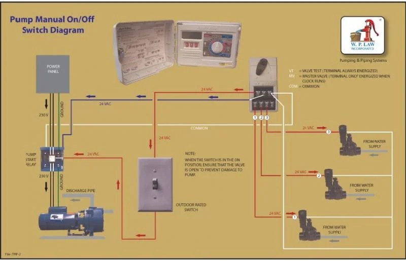
Web electrical relays for both low voltage (24v ac) control switching and high voltage (120v ac or 240v ac) main power contacts. Web the pump start relay easily connects to your timer in two locations, using normal irrigation valve wire. Locate the two thinnest wires extending from the pump start relay, and strip 1/2 inch of insulation from the end of both wires using the wire strippers.

Connect A Common Wire To The C (Common) Terminal Inside The Controller And Connect The Remaining Wire From The Pump Start Relay To The Mv Terminal.

Most timers do not provide sufficient voltage or current. Allows remote pump switching using 24v ac output from. Web a pump relay acts like a switch that the controller can turn on to provide power to the pump.

Web The Relay/Switch Is Operated (Turned On) By Connecting A 24 Vac Source To The Two Blue Wires Connected To The Relay Coil.

Web pump start relays must be mounted at a minimum of 15 feet from the timer and pump to avoid electrical interferences that cause malfunctions. Web munro smartbox pump start relay with pressure and temp sensors | mplc24t. The 1 items will be.

Determining The Pump Motor Circuit Size A Typical 1 1/2 Hp Motor Configured For 115 Volts Will Require A 20 Amp Circuit.

When a pump is to be operated. Since the controller outputs 24volts ac power, and most pumps. Web the pump start relay is an important component of any irrigation system that helps to ensure that the system runs smoothly and efficiently.

Web Use Wire Nuts To Make The Connections And Verify They Are Secure.

The pump motor wires from a 220 volt 1 1/2 hp sprinkler pump are both black wires and are on the right side of the relay.

Irrigation Pump Start Relay Wiring Diagram Wiring Schemas
Irrigation Pump Start Relay Wiring Diagram mobinspire
irrigation pump start relay wiring diagram
Irrigation Pump Start Relay Wiring Diagram One Most
irrigation valve wiring
Pump Start Relay Wiring Diagram Cadician's Blog
Irrigation Pump Start Relay Wiring Diagram Electrical wiring diagram
irrigation pump start relay wiring diagram

More Posts

5.3 Coil Pack Wiring Diagram

5.3 coil pack wiring diagram. Web chevy 5 3 vortec engine diagram wiring diagram show wiring diagram along with. Web web chevy 5.3 ignition coil wirin

5.3 Coil Pack Wiring Diagram

1756-If8 Wiring Diagram

0.33.2.1 mm² (22.14 awg) solid or stranded shielded copper wire rated at 90 °c (194 °f), or greater, 1.2 mm (3/64 in.) insulation maximum: 0.33.2.1

1756-If8 Wiring Diagram

John Deere D140 Wiring Diagram

Web the john deere d140 wiring diagram consists of two main sections: John deere l100 l110 l120 l130 lawn tractors. Web the john deere d140 wiring d

John Deere D140 Wiring Diagram

2002 Dodge Ram 1500 Radio Wiring Diagram

This printable was uploaded at december 08, 2022 by tamble in radio. Web 2002 dodge ram 1500 radio wiring diagram collection wiring diagram is a free

2002 Dodge Ram 1500 Radio Wiring Diagram

Wiring Diagram 6.5 Turbo Diesel Engine Diagram

Web ok thanks man we will see what happens. Web the common thing that is forgotten is the lifting eye must go. Web simpan simpan wiring diagram of f

Wiring Diagram 6.5 Turbo Diesel Engine Diagram

Wiring Subwoofer To 1 Ohm

Web how to wire 1 dual voice coil 1 ohm subwoofer in parallel, and series (wiring configurations) rockville audio 33.1k subscribers subscribe 10k vie

Wiring Subwoofer To 1 Ohm

36 Volt Curtis Controller Wiring Diagram

Web the controller also has features that allow can bus communication, has reduced wiring, and allows input and output sharing throughout the system.

36 Volt Curtis Controller Wiring Diagram

Rheem Water Heater Wiring

Web when putting together a wiring diagram for a rheem tankless water heater, there are a few common components that must be included. Web the wirin

Rheem Water Heater Wiring

Bilge Pump Float Switch Wiring

We show how to wire in a manual 12v bilge pump with a float switch, allowing the bilge pump to automatically activate when. Web in this video we are l

Bilge Pump Float Switch Wiring
popcontent